Shaders
Flitter supports running arbitrary “screen space” OpenGL shader programs as stacked image generators and filters.
This is similar to the operation of shader explorers such as
ShaderToy, but fully integrated into the Flitter
window hierarchy. This means Flitter shaders can manipulate the output
of other render nodes and be used as images or patterns in 2D
drawing, or as model textures in 3D rendering. For
instance, one might take a running !video, manipulate it
with a shader and then map the output onto the surface of a spinning sphere
in a !canvas3d.
!shader
The !shader node allows insertion of an arbitrary OpenGL shader program into
the window render tree. !shader nodes support the following
attributes:
size=WIDTH;HEIGHTThe output image size of this shader.
colorbits=[8|16|32]This overrides the color channel bit depth for this node’s output image (and any intermediate textures).
vertex=STRINGSpecifies the vertex shader program as a text string containing the GLSL code. Usually this would be read from a file with the
read()built-in function. If unspecified, a standard internal shader will be used.fragment=STRINGSpecifies the fragment shader program as a text string containing the GLSL code. Usually this would be read from a file with the
read()built-in function. If unspecified, the default simple compositing shader program will be used (which is fine if compositing is all you want to do).
Shader programs can access the image output of all child nodes declared
within the !shader node. The behaviour of these samplers for coordinates
outside the \([0,1]\) range can be controlled with either the attribute:
border=R;G;B;ASpecifies a color that will be returned for any out-of-range coordinates.
or with the attribute:
repeat=RX;RYSpecifies whether to wrap around (and therefore repeat) the image on the X and Y axes, if RX or RY is
true, or to return the color at the edge of the image, if RY or RX isfalse.
If neither border nor repeat is specified, then the default is for
out-of-range samples to return transparent (vec4(0.0)).
By default linear interpolation is used when sampling a child with a different size to the shader (for both minification and magnification). This can be turned off with the attribute:
nearest=BOOLEANSpecify
nearest=trueto use nearest pixel sampling instead of linear interpolation.
Shader programs
Shader programs are executed with the following assumptions:
The \([-1,1]\) screen-space vertices of a tri-strip covering the whole output frame-buffer is passed to the vertex shader as an
in vec2 positionvaryingThe default vertex shader passes standardized \([0,1]\) UV coordinates to the fragment shader via an
out vec2 coordvaryingThe fragment shader is expected to declare an
out vec4 colorvarying that will be written to the node’s output image
It is not usually necessary to specify a vertex shader program (with the
vertex attribute), as the default program is sufficient for most custom
shaders.
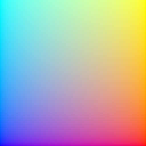
A minimum fragment shader would therefore look something like:
#version 330

in vec2 coord;
out vec4 color;

void main() {
    color = vec4(coord.x, coord.y, 1.0 - coord.x, 1.0);
}
If saved as the local file dummyshader.frag, this could be used in a
Flitter program:
!window
    !shader fragment=read('dummyshader.frag')
This simple example results in the output:
Standard uniforms
The vertex and fragment shaders have a number of available uniforms that will be automatically set if declared:
uniform vec2 sizeWill be set to the the pixel-size of the node’s output frame-buffer, the
coordUV coordinates can be multiplied by this to get actual pixel coordinates in the fragment shader.uniform float beatThe current beat counter.
uniform float quantumThe current quantum.
uniform float tempoThe current tempo.
uniform float deltaThe difference between the current beat counter and the its value on the last frame.
uniform float timeThe current frame time in seconds.
uniform int fpsThe target frame-rate.
uniform float performanceA value in the range \([0.5,2]\) that indicates how well the engine is managing to hit the target frame-rate.
uniform float alphaThe value of the
alphaattribute on the node or a default value of1. This is not automatically applied to the output of custom shaders and must be applied in the code if desired.uniform sampler2D[texture0|texture1| … ]These will be bound to the output image of each child node, in order of definition (and excluding any node that has a
hidden=trueattribute).uniform sampler2D lastIf declared, this sampler allows access to the final output of the shader from the previous frame. This allows for feedback loops to be constructed.
In addition to these, the shader program may declare arbitrary numeric uniforms
that can be set using attributes with matching names on the shader node.
float, vec2, vec3, vec4, mat3 and mat4 uniforms expect 1-, 2- , 3-,
4-, 9- and 16-item numeric vectors, respectively; arrays of these types expect
vectors with an appropriate multiple of these sizes. ints, doubles and
bools, plus their vec and mat variants are also supported. If an
attribute matching the uniform is not provided (or is of an incorrect type)
then all elements of the uniform will be set to \(0\).
Multi-pass shaders
A shader program can be executed multiple times per-frame, with the output image of each pass provided as an input to the next. This is controlled with the following attributes:
passes=PASSESThis specifies how many times the program should be executed. Default is
1if not specified.downsample_passes=PASS_NUMBERSThis specifies which (if any) passes to render with a smaller frame-buffer. It is specified as a vector of pass numbers, with the first pass being
0. For example1;2would specify the second and third pass. Default isnull, i.e., all passes will be rendered with asizeframe-buffer.downsample=DIVISORThis specifies how much to reduce the size of the output frame-buffer for down-sampled passes. It is specified as a divisor of the shader
sizeattribute. Default is2, i.e., the frame-buffer will be half the width and height, and therefore contain a quarter of the pixels. The value of thesizeuniform (if declared) will be the current pass’ output frame-buffer size.
For multi-pass shaders, the last sampler uniform provides access to the output
image of the previous frame only during the first pass (pass is \(0\)). For
subsequent passes, this sampler will access the output of the previous pass.
The following additional uniforms are available:
uniform int passesWill be set to the number of times that this shader will be executed, as specified by the
passesattribute.uniform int passWill be set to the number of the current pass, counting from
0.uniform int downsampleWill be set to the value of
downsamplefor down-sampled passes and1for normal passes.uniform sampler2D firstIf declared, this sampler allows access to the output of the first pass of the shader in the second and subsequent passes. During the first pass,
firstwill be a “zero” texture returning transparent for any coordinate.
The first sampler is specifically designed to allow an initial pass to build
up an output that will be used in the final pass of a shader in addition to
the output of a subsequent pass (with last). For filters like the built-in
!bloom filter, this initial pass is used to composite together
all of the child nodes before blurring. The final pass is then able to refer to
both the composited original and the blurred version.
All passes have access to the standard uniforms, including the samplers for all child nodes.
Shader templating
Flitter uses Mako templates internally to
allow shaders to adapt to different uses. Shader code will be evaluated using
this before being compiled. All of the uniform names described above (except
pass), and any custom attributes on the !shader node, are available as
values to the template logic.
In addition, the following special names are defined:
HEADERWill be set to either the standard OpenGL 3.3 version header or an OpenGL ES 3.0 version header, depending on whether the engine is runnning in ES mode or not. Shader code that is compatible with both of these versions (which includes all of the internal Flitter GLSL code) can use
${HEADER}as the first line to automatically adapt.child_texturesWill be set to a list of strings representing the uniform name for each of the sub-nodes of this shader, e.g.,
texture0. If the shader has no children then this list will be empty. A shader can use template<% for %/>loops to declare the correct number of sampler uniforms and handle a variable number of child nodes.
Note that if a shader is templated on a value, then it will be automatically recompiled if that value changes (or, to be precise, if the changed value causes a change in the evaluated source text). This will cause severe rendering performance problems if if occurs frequently. So one should avoid using a dynamically-changing value in the templating logic.
For instance, one might use these attribute values:
!shader fragment=read('myshader.frag') count=3 offset=-3;4.5
in a shader program as compile-time constants:
const int count = ${int(count)};
const vec2 offset = vec2(${float(offset[0])}, ${float(offset[1])});
Note
The current value of pass is not provided to the template engine – the same
shader program is used for each pass of a multi-pass shader. Multi-pass shader
programs should use the pass uniform and switch behaviour in code for
different passes.
Built-in image filters and generators
Flitter provides a set of useful built-in filters and generators, each of
which is implemented as a shader program. Each of these nodes, in common
with the default !shader program, accepts one or more child nodes
which will be composited together with the blend function controlled with
the composite attribute (default :over). All of the filters also support
the standard shader alpha attribute.
!transform
Composites its input nodes and then scales, rotates and translates its output.
This is similar to the !translate node in !canvas and !canvas3d. The
origin for all of these operations is the centre of the image.
scale=SX;SYSpecifies an amount to scale the image on the X and Y axes, default
1. Negative scales will flip the image on the X and/or Y axis.rotate=TURNSSpecifies a clockwise rotation in turns, default
0.translate=X;YSpecifies an amount to translate the image on the X and Y axes specified in pixels, with the Y axis pointing up, default
0.keystone=KX;KYSpecifies a “keystone” adjustment to the image, as a scaling factor along the \(x\) and \(y\) axes. A positive (small) value of KX will expand the left side of the image and compress the right side; a negative value will do the reverse. Similarly, a positive value of KY will expand the bottom of the image and compress the top; a negative value will do the reverse. Together these can be used to adjust for projection onto a tilted surface. They will normally have to be used with
scale=to avoid clipping of the image.
Areas “outside” the transformed image will be transparent by default. This can
be controlled with the border and repeat attributes described above for
!shader.
The order that the attributes are specified is important. Transforms are applied from the rightmost attribute (last) to the leftmost (first).
!vignette
A very simple vignette filter that composites its input nodes and then fades the edges of the output to transparent. It is controlled with the attributes:
inset=(0,0.5)Specifies the inset as a proportion of the height and width at which the fade-out will occur, default
0.25.fade=[:linear|:quad|:cubic]Specifies the function to use for the fade at the edges. Default is
:linear.
!adjust
The !adjust node applies color and luminance adjustments to the composited
input. It supports the following attributes:
color_matrix=MATRIXSpecifies a 3x3 matrix as a 9-vector to multiply each pixel by. The matrix is given in column-major order, so the first 3 values are multiplied by the red channel, the second 3 by the green channel and the last 3 values by the blue channel. The resulting color will be the vector sum of the results. Default is the matrix
1;0;0;0;1;0;0;0;1, i.e., no adjustment.brightness=LEVELSpecifies a brightness adjustment to be added to the color channels of each pixel. Default is
0.contrast=MULTIPLIERSpecifies a contrast adjustment as a multiplier. This defaults to
1. A contrast adjustment above 1 multiplies the value of each pixel around the midpoint, i.e., channels above 0.5 will become brighter and channels below 0.5 will become darker. A contrast adjustment below 1 will compress the dynamic range around 0.5.exposure=STOPSSpecifies an exposure adjustment in stops. An exposure adjustment of
1will double the color value of each pixel, an adjustment of-1will half the value of each pixel. Default is0.hue=DELTASpecifies a positive or negative hue adjustment in the useful range \((-0.5,0.5)\). All colors will be rotated around the standard HSV hue cylinder by this amount.
saturation=MULTIPLIERSpecifies an amount to multiple the saturation of each pixel by. Values less than
1will desaturate the image and values greater than1will over-saturate it. A value of0will convert the image to grayscale.shadows=STOPSSpecifies an exposure adjustment to apply to the darker parts of the input image (luminance < \(0.25\)).
highlights=STOPSSpecifies an exposure adjustment to apply to the lighter parts of the input image (luminance > \(0.5\)).
gamma=GAMMASpecifies a gamma curve correction to be applied after other color adjustments, Values less than 1 will lighten the output image and values greater than 1 will darken it.
tonemap=[:reinhard|:aces]If specified, then a tone-mapping function will be applied to map high dynamic range images into the \([0,1]\) range. The supported tone-mapping functions are: the Reinhard curve function, and a (close approximation of) the ACES filmic function. Default is no tone-mapping.
If tonemap=:reinhard then an additional attribute is supported:
whitepoint=LUMINANCEIf
whitepointis greater than1then the Reinhard curve will be modified to map input values atwhitepointto an output value of \(1\). Input values greater thanwhitepointwill saturate. Values close to1will result in no tone-mapping, large values will result in the standard Reinhard curve. Default is0, i.e., no curve modification.
The !adjust filter works in the following order:
un-premultiply alpha
apply
color_matrixapply
hueandsaturationapply
exposureapply
brightnessandcontrastapply
shadowsandhighlightsclamp negative values to zero
apply
gammaapply
tonemappre-multiply alpha
!blur
The !blur node applies a blur using a 2-pass (horizontal and vertical), 1D,
normalized Gaussian filter. It is controlled with the attributes:
radius=PIXELSSpecifies the size of the blur to be applied as a number of pixels in each direction. A value of
0will result in no blur being applied, which is the default ifradiusis not specified.sigma=SIGMASpecifies the sigma value for the Gaussian filter as a multiple of the
radius. This defaults to0.3and controls how quickly the blur will fall off.
If visible square edges form around bright spots then it may be necessary to
increase the value of radius and decrease the value of sigma. However, note
that the larger the value of radius, the greater the GPU computational
resource required to compute the blur.
!bloom
A !bloom filter creates a soft glow around bright parts of the image to
recreate the bloom effect commonly produced by camera lenses. It works by
applying an exposure adjustment to darken the entire image, then applies a
Gaussian blur and finally composites this together with the original image
with a lighten blend function.
The filter supports the same contrast, brightness and exposure attributes
as !adjust – except with exposure defaulting to -1 - and the
same radius attribute as !blur. The radius attribute must be
specified and be greater than zero for any bloom to be applied.
The default settings of the !bloom node assume that the input will contain
high dynamic range values, i.e., pixels with channel values much larger than 1.
This is common when lighting 3D scenes, but unusual in 2D drawings. For the
latter it may be better to set exposure=0 and use contrast values greater
than 1 instead.
The blur phases of this filter are run as down-sampled phases. By default
this frame-buffer will be half the width and height of size, but this can
be controlled with the downsample attribute.
!flare
A !flare filter attempts to emulate the tendency of optical lenses to produce
artefacts in the image, including “starbursts” and “ghosts”. The filter requires
a high dynamic range input (such as output by !canvas3d). The filter accepts
the following attributes:
threshold=LA luminosity threshold over which a pixel is deemed to be “bright”. Default is
1.attenuation=ATTENUATIONHow much to attenuate the flares from the brightness of the source. This is expressed as a power-of-2, so
1means half the (linear) luminosity and2means one-quarter the luminosity. Default is2.upright_length=LENGTHThe length of the vertical/horizontal starburst lines, expressed as a multiple of the shorter of the filter width or height. Larger values are more expensive to compute. Default is
0.25.diagonal_length=LENGTHThe length of the diagonal starburst lines, expressed as a multiple of the shorter of the filter width or height. Larger values are more expensive to compute. Default is
0.125.ghosts=NThe number of lens ghosts to add, between
0and6. The size, location and distortion of each ghost has been individually designed. Default is6. Reducing the number of ghosts has a slight performance benefit.aberration=RATIOHow much chromatic aberration (separation into spectrum lines) the ghosts will exhibit. This is expressed as a multiple of an internally-defined reasonable value. The default is
1. Values below1will result in tighter ghosts and0will turn off aberration completely (which has a slight performance benefit). Values above1may cause gaps to form between the 6 color separations used to emulate true chromatic aberration.
The lens flare phases of this filter are run as down-sampled phases. By default
this frame-buffer will be half the width and height of size, but this can
be controlled with the downsample attribute. As this filter is very expensive
to compute, setting downsample=3 or downsample=4 can make a significant
difference to GPU load – particularly if the filter size is large.
!edges
The !edges node applies a simple edge-detection filter by blurring the input
and then blending this with the original image with a difference blend
function.
!edges supports the same radius and sigma attributes as !blur
and, again, radius must be greater than zero or the output will be blank. In
addition, !edges also supports the attribute:
mixer=RATIODefines how much of the original image to mix into the output. Default is
0, which means only the edge-detection output is produced. A value of0.5will produce an even mix of the original image and the edge-detector output.
The blur phases of this filter are run as down-sampled phases. By default
this frame-buffer will be half the width and height of size, but this can
be controlled with the downsample attribute. For crisper edges, set
downsample=1.
!feedback
The !feedback node simulates the effect of the analogue video feedback loop
formed by pointing a camera at a screen and mixing this with this input signal.
The following attributes control this mixing and the transformation applied to
the feedback signal:
timebase=BEATSSpecifies a number of ticks of the beat counter that controls the application of the other attributes. This defaults to
1beat.mixer=AMOUNTSpecifies the mix between the feedback signal and the input signal over
timebasebeats.translate=X;YSpecifies how far the decaying feedback signal will move in pixels per
timebasebeats using the canvas coordinate system (i.e., origin in the top left). Defaults to0.scale=SX;SYSpecifies how much the decaying feedback signal will be scaled as a multiple over
timebasebeats. Defaults to1.rotate=TURNSSpecifies how much the decaying feedback signal will be rotated clockwise as a number of full turns per
timebasebeats. Defaults to0.
Note
The !blur, !bloom, !edges and !feedback shader programs use samplers
that default to sampling the edge color for pixels beyond the edge of the image
as this produces the best results for those programs. This can be controlled
with the border and repeat attributes as described above for
the !shader node.
!noise
The !noise node is primarily an image generator that generates 2D slices
through OpenSimplex 2S 3D (“improved
XY”) noise. It is controlled with the following attributes:
seed=SEED!noisegenerates reproducible output with the same input values. Supply a unique vector with theseedattribute to generate different outputs, defaults to the null vector if not supplied.components=1..4Specify how many distinct noise planes to create, default
1. Each will be assigned to one channel of the output image (in the order R, G, B, A).octaves=OCTAVESSpecify how many octaves of noise to generate, default
1.roughness=ROUGHNESSEach additional octave of noise has its input coordinate space and output value scaled by
roughness, default0.5.scale=SX;SY;SZSpecifies a scaling vector to be applied to the X, Y and Z coordinates passed into the noise function, default
1.origin=X;YSpecifies an offset for the pre-scaled X and Y input values, default
0. The pre-scaled X and Y coordinates are in pixels from the top left.z=ZSpecifies a pre-scaled Z coordinate for the plane to be calculated, default
0.multiplier=MULTIPLIERSpecifies a multiplier for the final noise value, default
0.5.offset=OFFSETSpecifies an offset to be added to the multiplied noise value before writing to the output image, default
0.5.default=DEFAULTSSpecifies the default values of the color channels as a 4-vector (in the order R, G, B, A). These will be used for any channels not filled-in with noise values (see the
components=attribute above). The default value is1, meaning all unused channels will have the value1.
OpenSimplex 2S noise values are in the range \((-1,1)\). The default values for
multiplier and offset are designed to adjust the noise range into the
standard \((0,1)\) range for color values. However, with an HDR image format
(i.e., the default colorbits=16) there is no particular need to restrict the
noise values to this range – particularly if they are subsequently being used
as the input to another shader. Setting multiplier=1 and offset=0 will
return unmodified noise values.
If one or more child textures are defined within the !noise node then they
will be composited together and the resulting R, G, and B values passed into
the noise function as X, Y and Z offsets, controlled with the attribute:
tscale=TX;TY;TZSpecifies a scaling factor for the RGB values read from the input image into offsets that will be added to the pre-
scaled noise coordinates, default1.