3D Rendering
Overview
3D rendering in Flitter uses a forward renderer with a physically-based rendering (PBR) model. Shadow-casting is not supported. Transparency is supported using ordered rendering.
3D Canvases
A 3D canvas is added into the window rendering tree with a
!canvas3d node. For example:
!window size=1920;1080
    !canvas3d
        …
!canvas3d differs from !canvas not just in number of dimensions, but in the
entire rendering approach. While the contents of a regular 2D canvas are mostly
interpreted as individual drawing instructions, the contents of a 3D canvas
build a scene containing models, lights and one or more cameras. This scene is
then passed to one or more 3D shader programs to render.
The !canvas3d node has only one attribute that is unique to it:
camera_id=IDThis specifies the camera to use for the output of this node in the window rendering tree. If not specified, then the default canvas render-group camera is used.
Beyond this single attribute, the !canvas3d node combines the functionality of
transforms, render groups, cameras
and materials. All of the attributes listed below for those nodes
are also supported on the !canvas3d node.
Transforms
The !transform node applies changes to the local transformation matrix that
defines the coordinate system for all of the enclosed nodes. The supported
attributes are:
translate=X;Y;ZMoves the origin to X
;Y;Z in the current coordinate system.scale=sX;sY;sZScales the coordinate system so that each unit of \(x\), \(y\) and \(z\) become \({sX} \cdot x\), \({sY} \cdot y\) and \({sZ} \cdot z\) in the current coordinate system. If given as a single item vector then scale all axes by that amount.
rotate=tX;tY;tZAdds three rotation steps into the local transformation matrix, rotating by \(tZ\) turns around the \(z\)-axis, then \(tY\) turns around the \(y\)-axis and then \(tX\) turns around the \(x\)-axis. Rotates equally around all axes if given as a single item vector.
rotate=qW;qX;qY;qZAdds a rotation step into the local transformation matrix described by a unit quaternion. See Quaternion functions.
rotate_x=tXAdd a rotation step around the \(x\)-axis alone.
rotate_y=tYAdd a rotation step around the \(y\)-axis alone.
rotate_z=tZAdd a rotation step around the \(z\)-axis alone.
shear_x=kY;kZAdd a shear transformation of the \(x\)-axis in terms of the \(y\) and \(z\) axes.
shear_y=kX;kZAdd a shear transformation of the \(y\)-axis in terms of the \(x\) and \(z\) axes.
shear_z=kX;kYAdd a shear transformation of the \(z\)-axis in terms of the \(x\) and \(y\) axes.
matrix=MMultiply the current local transformation matrix by the matrix M given as a 16-item vector in column-major-order.
The transform attributes honour the order that they are applied to a
!transform node. So the matrix is updated left-to-right in the following:
!transform translate=10;20;30 rotate_x=0.25 scale=1;2;1
    …
and is equivalent to:
!transform translate=10;20;30
    !transform rotate_x=0.25
        !transform scale=1;2;1
            …
From the perspective of the world coordinate system, this transform results in the contained models being scaled by double in their \(y\)-axis, then rotated by 0.25 turns around their \(x\)-axis and then offset by 10;20;30.
The transform attributes are also valid on !canvas3d and !group nodes,
applying to everything in the scene or to the contents of that render group.
Render Groups
A render !group bundles up part of a scene that will be rendered together,
optionally with a custom shader program. A default render group is created
at the same time as the canvas and is configured by adding render-group
attributes to the !canvas3d node. However, additional render groups may be
created inside the canvas or nested within another group. Groups may be placed
within !transform or !material nodes and the local transformation matrix
and material properties will be inherited by the new group. Transform and
material attributes may also be provided on a group node.
If any lights are defined inside a render group, those lights will apply
only to the models inside that group and models inside any contained groups.
As the top-level !canvas3d node is itself a render group, any lights defined
at the top level affect the entire scene.
Pulling models and lights into a !group is a useful way to limit lighting
effects within the scene. As there is no support for shadow-casting in
Flitter, this can be particularly useful to limit the effect of enclosed
lights that shouldn’t affect the rest of the scene.
The supported attributes are:
max_lights=NSet the maximum number of lights that the shader program will support. Additional lights beyond this number will be ignored when rendering this group. The default is 50. The upper limit is dependent on the GPU and driver, but is typically a few hundred. Changing this attribute will cause the shader program to be recompiled.
composite=[:over|:dest_over|:lighten|:darken|:add|:difference|:multiply]Control the OpenGL blend function used when rendering models that overlap each other. The default is
:over.depth_sort=[true|false]Controls the depth-sorting phase of instance ordering. Setting this to
falsewill result in instances of the same model being dispatched for rendering in an arbitrary order and will disrupt correct handling of transparent and translucent objects. The default istrue.depth_test=[true|false]Turn off OpenGL depth-testing for this render group if set to
false, the default istrue. Settingdepth_testtofalsewill also disable depth sorting (as above). Generally this is only useful when combined with a blend function like:addor:lighten.face_cull=[true|false]Turn off OpenGL face-culling for this render group if set to
false, the default istrue. Model faces are fed into the shader program in an arbitrary order.cull_face=[:back|:front]Assuming face-culling is enabled (as above), this specifies which faces of the models to cull. The default is
:back, but specifying:frontcan be useful for special effects or for use with custom shaders.
Note
Setting cull_face=:front is similar to, but not the same as inverting all
of the models in a render group. Inverting a model reverses the face winding
and the normal direction of each vertex. Culling the front faces results in
the back faces being drawn using their original normals, i.e., they will only
be lit by lights behind the model (or ambient lighting).
vertex=TEXTSupply an override vertex shader as a text string containing the GLSL code. Usually this would be read from a file with the
read()built-in function. If unspecified, the standard internal PBR shader will be used.fragment=TEXTSupply an override fragment shader as a text string containing the GLSL code. Usually this would be read from a file with the
read()built-in function. If unspecified, the standard internal PBR shader will be used.
Note
Supplying your own shader program is beyond the scope of this document, but there is an example of doing this available in the flitter-examples repo.
Also worth noting is that, while Flitter internally keeps to OpenGL version
3.3, you should be OK to use a higher version number in your shader #version
specifier if your platform supports it. On macOS, the highest OpenGL version
supported is 4.1.
Instance Ordering
Within a render group, all instances of specific models are dispatched to the GPU in one call, with per-instance data providing the specific transformation matrix and material properties. For each model, any instances that have no transparency or translucency are sorted from front-to-back before being dispatched. This allows the OpenGL early depth-testing to immediately discard fragments of objects that are hidden by a nearer object.
After non-transparent instances have been rendered, all instances with translucency are collected together in front-to-back order and rendered into auxiliary buffers to collect back-face lighting and depth data. All instances with either transparency or translucency are then rendered in back-to-front depth order.
Depth-buffer writing is turned off when rendering instances with transparency. This means that all transparent objects will be rendered fully even if they intersect with one another, overlap in non-trivial ways. However, the depth buffer is still honoured for deciding whether a fragment is to be rendered and so transparent instances occluded by non-transparent instances will be hidden.
Instance depth sorting is done by computing a bounding box for the model
(aligned on the model axes) and then finding the corner of that box nearest to
the camera for each instance. This will generally work for well-spaced models
but may fail to derive a correct ordering for close/overlapping models causing
transparency to render incorrectly. Depth sorting can be controlled for a
specific render group with the depth_sort attribute.
Turning off depth sorting will cause all instances to be dispatched to the GPU
in an arbitrary order instead of front-to-back or back-to-front, regardless
of whether they have transparency or translucency. For non-transparent objects
this will have no visual effect as the depth buffer will resolve overlaps.
However, transparent and translucent objects will likely render incorrectly,
showing the wrong objects behind. When rendering large numbers of small,
non-transparent objects, it may be faster to turn off depth sorting and let the
depth buffer handle overlaps. If depth buffer testing has been disabled with
depth_test=false, then depth sorting is also automatically disabled.
Cameras
A default camera is created at the same time as the canvas and is configured
by specifying camera attributes on the !canvas3d node. Additional cameras
can be defined anywhere inside the scene tree where a model can
be placed. Cameras defined in this way count as objects within the scene and so
will respect any local transformation matrix in effect.
Any attributes not specified on a !camera node will take the same values as
the !canvas3d node default camera. The defaults given below apply to any
attribute not specified there either.
The supported attributes are:
id=IDThis is a string (or symbol) identifier that can be used to select this camera as the primary output by specifying the same ID as the
camera_idattribute of!canvas3d.size=WIDTH;HEIGHTThis specifies the pixel dimensions to render this camera view at. The value will default to the size of the parent node of
!canvas3din the window rendering tree.secondary=[true|false]If set to
true, this camera will be rendered regardless of whether it is the current primary camera and the resulting output will be made available as a texture for referencing, either with a!referencenode within the window rendering tree, with atexture_idattribute on an!image, or even as a texture mapped on a model. This defaults tofalseand is not inherited from the default camera.position=X;Y;Z |viewpoint=X;Y;ZThe position of this camera, respecting any local transformation matrix. It is common to use
viewpointwhen specifying this attribute on a!canvas3dnode to make clear that this is referring to the position of the camera.focus=X;Y;ZA point that the camera is aimed towards, respecting any local transformation matrix. The direction of this from the camera
positionprovides the camera view direction – its z-axis.up=X;Y;ZA vector giving the y-axis of the camera. This is a direction not an absolute position. It respects any local rotations. If this direction is not at right angles to the camera view direction, then it will be corrected while maintaining the plane formed by the two.
Note
position, focus and up are all converted into the world coordinate system
before being stored as camera properties. This means that inherited defaults
will be in the world coordinate system.
This means that one can specify a focus for the default camera on !canvas3d
and then place another moving camera in the scene with a constantly changing
local transformation matrix, and have this camera continue to point towards the
default focus point regardless of its local position.
orthographic=[true|false]Specifies whether this camera uses an orthographic (non-perspective) projection. The default is
false.fov=FOVSpecifies the field-of-view for perspective cameras (
orthographic=false) in turns, i.e., 90° is0.25– effectively the zoom vs wide-angle setting of the camera.fov_ref=[:horizontal|:vertical|:diagonal|:narrow|:wide]Specifies the reference length for field-of-view. The default is
:horizontal, meaning thatfovspecifies the horizontal field-of-view. The special values:narrowand:wideallow one to refer to the narrower or wider of the horizontal and vertical camera view dimensions. This is useful if the camerasizemight change between portrait and landscape aspects and a minimum or maximum field-of-view is desired.width=WIDTHSpecifies the width of the camera view in the world coordinate system. An orthographic camera is effectively a rectangle that projects in the camera view direction. The aspect ratio of that rectangle is taken from the
sizeattribute, this attribute gives the actual width of the rectangle.near=NEARSpecifies the near clip plane of the camera. Anything on the near side of a plane (orthogonal to the camera view direction) at this distance from the camera in the world coordinate system will not be rendered.
far=FARSpecifies the far clip plane of the camera. Anything on the far side of a plane (orthogonal to the camera view direction) at this distance from the camera in the world coordinate system will not be rendered.
Note
For a perspective camera, it is important that the values of near and far
are not too small or too big, respectively. Otherwise the OpenGL coordinate
calculations can suffer from precision problems that can affect the rendering.
It is best to keep these numbers to just either side of the expected scene
dimensions.
monochrome=[true|false]If set to
truethen the output of the camera will be grayscale. The RGB values will be converted into a single luminance value that will then be used for each fo the RGB channels of the output. The default isfalse.tint=R;G;BA tint value that will be multiplied into all of the pixel RGB values. This can be used to do simple whitepoint correction or to achieve particular effects. This can be combined with
monochromeand will happen after the RGB values have been turned into grayscale values – as such it can be used to produce effects like sepia toned monochrome output. The default is1;1;1, i.e., no tinting.colorbits=[8|16|32]The bit depth of the output color channels. The canvas default is taken from its parent(s) in the window rendering tree. If not specified on any ancestor node, it defaults to
16bits.
Warning
It is a bad idea to use 8-bit color depth with the 3D renderer. All rendering calculations are done in linear color space and the conversion to monitor sRGB logarithmic space is done as a final window rendering step. Starting with only 8-bits of color resolution will produce visible banding in darker areas of the window, as this range gets expanded by the logarithmic conversion while the bright range is compressed. Working in 16-bits provides ample precision to ensure that the final sRGB output is smooth.
The second advantage to working in 16-bits is that the color space expands out to half-floats instead of 256-level \([0,1]\) pseudo-floats. This means that channel values greater than 1 won’t clip. As the lighting calculations often produce high brightness values – particularly in specular reflections or near point and spot lights – clipping severely reduces your room to correct for this with a tone-mapping filter or deliberately exploit it with a bloom filter.
samples=[0|2|4|8| … ]Controls the amount of multi-sampling to do. The default is
0(none). Generally4works well with most GPUs and is really good value-for-money – particularly if you have a lot of small/fine models.fog_color=R;G;BThe color to use for fog. Fog is only enabled if
fog_maxis greater thanfog_min. If so, the camera frame-buffer will be filled with this color, instead of transparent pixels, before rendering starts and rendered fragments will be mixed with the fog color depending on their distance from the camera. The default color is black,0;0;0.fog_min=MINThe minimum distance before fog begins to apply. Defaults to
0.fog_max=MAXThe maximum distance at which point all fragments will be rendered as
fog_color. Defaults to0, which means fog is not applied.fog_curve=EXPONENTThe fog calculation takes the relative distance between
fog_minandfog_maxin the range \([0,1]\) and raises it to this power before using that as the constant for mixing the fragment color withfog_color. The default is1, i.e., linear fog. You may find that2gives a more authentic result.
Lights
Lights are all specified with the !light node, which supports the following
attributes:
color=R;G;BSpecifies the light color and brightness. These values may, and often will need to be, significantly greater than
1. In fact, lights may also be negative as there’s nothing in the maths that stops this. While not being physically realistic, this can be used for some interesting effects. A light withcolorequal to0will be completely ignored, and this is the default value if the attribute is missing.position=X;Y;ZSpecifies the location in space of a point or spot light, respecting any local transformation matrix.
start=X;Y;ZSpecifies the start point of a line light, respecting any local transformation matrix.
end=X;Y;ZSpecifies the end point of a line light, respecting any local transformation matrix.
radius=RSpecifies the radius of a point or line light. This defaults to zero.
direction=X;Y;Z |focus=X;Y;ZSpecifies the direction that this light shines, either as a direction vector or as an absolute position
focus.focuscan only be used ifpositionhas also been specified (i.e., for spotlights).directionrespects any local rotations andfocusrespects the full local transformation matrix.outer=0…0.5Specifies the angle of the cone of a spotlight beam, in turns. Defaults to
0.25, i.e., 90°, which means the light will shine out 45° all around from the central direction line.inner=0…outerSpecifies the portion of a spotlight beam angle that is at full brightness, in turns. Outside of this angle, the light will dim towards 0 at
outer. Defaults to0.falloff=A;B;C;DSupplies the coefficients for the light fall-off equation:
\[{light} = {\textbf{color} \over {A} + {B}\cdot{d} + {C}\cdot{d^2} + {D}\cdot{d^3}}\]Defaults to
0;0;1;0, i.e., inverse-squared fall-off with distance. If models can pass close to lights and the subsequent very bright spots need to be avoided, then it can be useful to introduce a constant component to this with something like1;0;1;0.
Light Types
Flitter supports four kinds of lights, based on which of the above attributes have been specified:
- Ambient
If only
coloris given then this light is an ambient light that will fall equally on all models in the render group in all directions. As such this normally has only small values forcolor.- Directional
If
directionis given in addition tocolorthis this light is a directional light that shines everywhere with equal brightness in one direction. As for ambient lights, the values ofcolorwill normally be smaller than1. This light type is typically used for large, very distant light sources, like sunlight.- Point (/ Sphere)
If
positionis given in addition tocolorthen this light is a point light that shines outwards in all directions fromposition. The light brightness will fall-off with distance according tofalloff. Due to fall-off, it is common for thecolorvalues to be very large. A point light may have aradiusattribute specified. If this is non-zero, then the light will be modelled as a sphere rather than a strict point. This will affect how light falls on objects close to the “surface” of the light and also affects the apparent size of specular reflections in shiny objects.- Line (/ Capsule)
If
startandendare both specified, then the light is a line that extends between these two points. Light spreads outwards from this line in all directions. Like point lights, line lights may also have aradiusattribute specified. If this is non-zero then the light will be modelled as a capsule rather than a strict line.- Spot
If both
positionanddirection(orfocus) are specified then this light is a spotlight that shines frompositionindirection. The beam will spread outwards in a cone with angleouterand will fall-off according tofalloff. As for point lights, it is common for thecolorvalues to be very large.
While lights are specified as objects in the scene, they are not rendered
themselves and only affect models in the scene. If a visible representation of
a light is required then one would normally need to place a model at the same
location as the light and give it an emissive material color.
As long as this model is convex, and the light is positioned within it, the
light will not affect the model.
Flitter does not support shadow-casting and lights will illuminate all models in the render group regardless of occlusion.
Warning
Point lights with a radius and linear lights (with or without a radius) are loose approximations rather than accurate lighting models. The implementation is designed to be low effort to calculate in the shader, and involves a 2-pass calculation – for diffuse and specular lighting – using per-fragment dynamic positioning of a point light.
Materials
Materials specify the surface properties of models. A “current” material is
maintained alongside the local transformation matrix. This material is
changed by specifying properties using the attributes below on !canvas3d or
!group nodes, on specific !material nodes, or directly on models.
The !material node only makes changes to the current material and this then
applies to any models defined as children of that node. !material nodes may
be intermixed in the tree with !transform nodes, i.e., a model could be placed
within a !material node inside a !transform node, or within a !transform
node inside !material node. This allows for significant flexibility in
combining multiple models that share material or location properties.
Flitter uses physically-based rendering and so the material properties are defined in terms of that standard workflow.
The supported material attributes are:
metal=[true|false|0…1]Specifies whether the material is a metal or a dielectric. Logically, this value is a boolean. However, values between
0and1are supported to represent a mix of these two properties. This is primarily useful when a metal texture map is used, to allow for smooth edge conditions between areas of metal and some other material (corrosion for example).color=R;G;BSpecifies the albedo color of dielectrics or the base reflectivity of metals. The canvas default is
0;0;0. These values would not normally be greater than1, but there is no limit defined and so models can reflect more light than falls on them for special-effect purposes.ior=IORSpecifies the index-of-refraction of the material surface. This alters how light is scattered off the surface. The canvas default is
1.5, which is a reasonable value for most solid materials. The scene “air” has a value of 1 for the purposes of PBR calculations.roughness=0…1Specifies the roughness of the material, where
0is a perfectly shiny surface and1is completely matt. In practice, roughness values below about \(0.25\) will result in very bright reflections. The canvas default is1.ao=0…1Specifies an ambient occlusion level for the material. Ambient lights will be multiplied by this value when being applied. This is really only useful when this property is texture mapped, where it allows for parts of a model to be occluded. The canvas default is
1.emissive=R;G;BSpecifies an amount of color that this object emits. This does not make the model into a light, it only affects how the surface of the model is rendered. These values may be greater than
1, and this is not an uncommon thing to do if tone-mapping or bloom-filtering is in use. The canvas default is0;0;0.transparency=0…1Specifies how transparent this material is, with
0being not transparent at all and1meaning fully transparent. Flitter does not support refraction, so objects will not appear realistically “glassy”. Any transparency value greater than0will affect the model render order. Transparency applies only to diffuse light scattered from the surface, emissive lighting and specular reflections will be calculated as normal. The canvas default is0.translucency=TRANSLUCENCYSpecifies how translucent this material is as a distance (in the world coordinate system) over which half of the light falling on the back faces of the object will pass through it. The canvas default is
0, meaning no translucency. At low levels of translucency, light will be scattered and will glow through the edges/thin-parts of objects. At higher levels of translucency light will be scattered less and the object will become increasingly transparent. Setting this to non-zero both affects the model render order and forces an additional render pass to determine the thickness of the object and the light falling on the back faces.
Note
For emissive=\(c\), surface normal \(\vec{N}\) and viewer direction \(\vec{V}\),
the surface emissive lighting color \(e\) will be calculated with the formula:
The intent is to introduce a directional component to emissive lighting that ensures bright surfaces retain some definition – rather than being uniformly lit – while still coloring the entire surface.
Texture Mapping
In addition to the above single value attributes, material nodes support specifying textures to be used for per-fragment material properties. Each of these attributes takes a string or symbol value identifying a node elsewhere in the window rendering tree that will be used as the input texture (including the output of secondary cameras).
The simplest way to load a collection of images to use as textures is to place
!image nodes in an !offscreen. See the textures
example
in the main repo for how to do this.
color_id=IDSpecifies the ID of a node to use for the material
colorproperty. (May also be specified astexture_id=for compatibility with an older version.)metal_id=IDSpecifies the ID of a node to use for the material
metalproperty. (May also be specified asmetal_texture_id=for compatibility with an older version.)roughness_id=IDSpecifies the ID of a node to use for the material
roughnessproperty. (May also be specified asroughness_texture_id=for compatibility with an older version.)ao_id=IDSpecifies the ID of a node to use for the material
aoproperty. (May also be specified asao_texture_id=for compatibility with an older version.)emissive_id=IDSpecifies the ID of a node to use for the material
emissiveproperty. (May also be specified asemissive_texture_id=for compatibility with an older version.)transparency_id=IDSpecifies the ID of a node to use for the material
transparencyproperty. (May also be specified astransparency_texture_id=for compatibility with an older version.)
For color properties, the color is read directly from the texture. For non-color properties, the texture color is converted into a luminance value in the range \([0,1]\) and this is used for the property value.
All textures support an alpha channel. If this is less than \(1\), the value read
from the texture will be mixed with the respective single-value property from
the !material node (or the default). This allows, for example, a generic
“corrosion” or “dirt” texture with alpha transparency to be applied over
multiple instances of a model with different base colors.
The behaviour of the texture samplers can be controlled with the attributes:
border=COLORSpecifies a 4-vector color to be returned for texture coordinates outside of the \([0,1)\) range.
repeat=REPEATSpecifies a 2-vector of boolean values (i.e.,
false/0ortrue/1) for whether to repeat the texture on the \(U\) or \(V\) axis (respectively) or to clamp to the edge color of the texture.
The default is to clamp to the edge color, i.e., repeat=false. Specifying
the border attribute will override any setting for repeat.
Models
Actual renderable objects are placed in the scene with model nodes. There are a number of built-in primitive models and the ability to load an arbitrary triangular mesh from a file. All model nodes share a set of common attributes:
position=X;Y;ZSpecifies a local position for the origin of the model. This will be
0;0;0if not specified. This allows models to be easily positioned using an enclosing!transformnode instead.size=sX;sY;sZSpecifies a “size” for the model, which is just a scaling factor. Makes most sense when the model is unit-sized. The default is
1;1;1.rotation=tX;tY;tZSpecifies rotation (in turns) around the respective axes. The default is
0;0;0.
These three attributes are equivalent to:
!transform translate=X;Y;Z rotate=tX;tY;tZ scale=sX;sY;sZ
    …
However, the position, size and rotation attributes may be specified in
any order and the resulting local transformation matrix will be calculated
with the transforms applied in this specific order.
An alternative to position/size/rotation placement is the attributes:
start=X0;Y0;Z0Specifies the local position of the model point \((0, 0, -0.5)\).
end=X1;Y1;Z1Specifies the local position of the model point \((0, 0, 0.5)\).
radius=RSpecifies a model \(x\) and \(y\)-axis scale.
These attributes are specifically designed to be used with unit-radius and
unit-length models that have their origin at the centre of their bounding box
and their length along the \(z\)-axis, which matches the !cylinder and !cone
primitives below. The attributes encompass a position,
rotation and \(z\)-axis scaling with start and end, and then a scaling in
the other two axes with radius.
In addition to these transformation attributes, all models may have material attributes that provide material properties specific to the model.
Model data is aggressively cached but automatically rebuilt as required. This includes automatically reloading external models if the file modification time-stamp changes. Multiple instances of the same model are collated and dispatched simultaneously to the GPU.
Primitive Models
The Flitter primitive models are generated on-the-fly and all of them have their origin at the centre of their bounding box.
!boxThis is a unit-edge cube, i.e, the corners are at \((±0.5, ±0.5, ±0.5)\).
!sphereThis is a unit-radius sphere (strictly speaking, the surface is made up of triangular faces with vertices on this sphere). The sphere is constructed from eight subdivided octants with overlapping seams at the planes formed by the model \(x\), \(y\) and \(z\) axes.
!cylinderThis is a unit-radius and unit-height cylinder with its axis of rotational symmetry along the \(z\) axis.
!coneThis is a unit-radius and unit-height cone with its point in the \(+z\) axis direction.
The model nodes !sphere, !cylinder and !cone all support an additional
attribute:
segments=NThis specifies the number of segments the model should be generated with. This is the number edges around the top and bottom sides of a cylinder, the bottom side of a cone or around the equator of a sphere. The default is
64, which is appropriate for most uses but may need to be increased for models being viewed at very close distances. The minimum number of segments for a!cylinderor!coneis2(resulting in a flat double-sided rectangle or triangle respectively) and the minimum for a!sphereis4(resulting in an octahedron). As a!sphereis made up of octants,segmentsis constrained to be a multiple of 4 and will be rounded up to the nearest multiple.
Warning
The number of model vertices and faces scales linearly, or quadratically in the
case of spheres, with the number of segments and so this should be no greater
than that necessary to eliminate obvious visual artefacts.
That said, when rendering large numbers of a particular kind of primitive, it
is better to use the same value for segments for all of them, as this results
in the instances sharing the same underlying model and allows the engine to
dispatch them for rendering simultaneously.
Primitive model texture mapping
The primitive models are all designed for texture mapping. The UV mapping schemes are as follows:
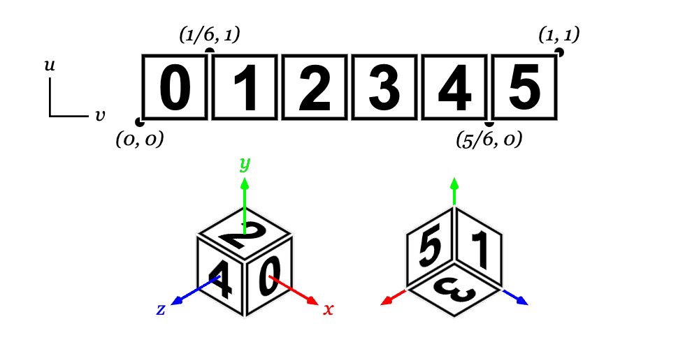
!boxuv_map=:standardThis is the default mapping for
!box. Each face of the box is mapped to a \(1 \over 6\) vertical slice of the \([0,1]\) UV space. From left-to-right, the mapped faces are +X, -X, +Y, -Y, +Z and -Z – all as viewed from the outside of a cube in a right-hand coordinate system. The +X, -X, +Z and -Z faces have their “up” direction as the \(+y\) axis, the +Y face up is the \(-z\) axis and the -Y face up is the \(+z\) axis.
!boxuv_map=:repeatThe faces (and their “up” directions) are as for
uv_map=:standardabove, but the UV coordinates map each face to the full \([0,1]\) UV space, repeating the same texture on each face.!sphereUV coordinates use the Equirectangular projection with the model \(+z\) axis being “North” and the left edge of the texture aligned to the model \(+x\) axis and then wrapped anti-clockwise. If the zero longitude line is in the centre of the image (common for maps) then this line will end up aligned to the -x axis. This projection is common for planetary mapping and 360° photography. The latitudinal strips at the poles are each made up of four triangular faces with their tips meeting at the pole. This means that there are four opposing triangular sections of the map missing at both poles. The other latitudinal strips are complete but, as the number of triangles decreases towards the poles, the mapping is not even and lines of longitude will tend to kink further from the edges of the octants. Both of these issues will be more apparent at lower segment counts.
!cylinderUV coordinates are similar to an Equirectangular projection, with the bottom circle mapped to the lower \(1/4\) of the UV space, the top to the top \(1/4\), and the middle \(1/2\) wrapped around the sides of the cylinder. The sides are made up of triangularized quads that cover the entirety of the middle half UV space, but the top and bottom use triangular faces and so half of each of the top and bottom quarter spaces is excluded from the map.
!coneUV coordinates are similar to
!cylinderexcept that the upper \(3/4\) of the UV space are wrapped around the sides of the cone and the sides also use triangular slices of the UV space and therefore exclude one half of the map.
Custom Models
Custom mesh models may be created with the !model node. These can be
specified either as an external file containing vertices and faces or directly
as vectors.
To load an external model use the attributes:
filename=FILENAMESpecifies the model file to load, relative to the program path. The model will be automatically reloaded if this file changes.
repair=(true|false)If set to
true, attempts to repair the mesh by merging duplicated vertices removing duplicate or degenerate faces, and fixing normal directions and face windings. This can be useful if a loaded mesh is rendering incorrectly or is failing with constructive solid geometry operations. Default isfalse.
Meshes are loaded using the trimesh library and so
Flitter supports all of the file-types supported by that, which includes
OBJ and STL files. No material properties are loaded, just the triangular mesh,
so you will need to re-specify the material properties using a !material
node or with material attributes on the !model node itself.
To create a mesh from scratch use the attributes:
vertices=VERTICESProvides a 3n-vector of x, y and z model coordinates for n vertices.
faces=FACESProvides a 3m-vector of vertex numbers in the range [0,n) giving the corner vertices of m triangular faces.
Note that face vertices should be specified in an anti-clockwise direction as viewed from outside the model for the surface normals to be computed correctly.
Custom vertex models are cached and so, while it is possible to animate a model by constantly changing the vertices or faces, this will increase memory usage.
Controlling Model Shading
The primitive models are all designed with seams and vertex normals so that they render in a sane way: flat sides are uniformly flat and curved sides have interpolated normals that ensure they render smoothly.
You can probably assume that any external model you load is designed similarly, but there are a few model shading controls that can be used to force specific shading behaviour by generating a new, derived model. As with all models, the results of these operations are cached.
flat=[true|false]Setting
flat=truewill generate a new model with all faces disconnected so that each face shades as a separate flat surface.
Note
Flat shading will create a large number of duplicate vertices. The new model will have the same number of faces, but three distinct vertices per face.
For finer-grained control over shading, there is an edge snapping algorithm that will take a smooth-shaded model, find sharp edges and split them into seams. This algorithm can be controlled with the following attribute:
snap_edges=0…0.5This specifies the minimum edge angle (in turns) at which to snap. It represents the difference between the normals of the adjoining faces, so an angle of
0would mean that the two faces are in the same plane,0.25would mean that they are at right angles to one another. Specifying0.5will disable the algorithm completely,0will cause all edges to be snapped (which is equivalent to specifyingflat=true).
A model can also be inverted with the attribute:
invert=[true|false]Setting this attribute to
truewill flip all vertex normals and face windings.
The result of inverting a model is that the insides of the back faces of the model will be rendered instead of the outside of the front faces. This can be used to render specular reflections on the back faces of transparent objects (by rendering the object twice: normal and inverted) or to create environments (e.g., by texture-mapping a large inverted sphere that encloses the scene).
If the texture-mapping UV coordinates for a model are missing or incorrect, then a new set can be calculated automatically.
uv_remap=MAPPINGSetting this attribute will replace the UV coordinates for the model with a new computed mapping.
The supported mappings are:
:sphereThis notionally draws a ray from the origin of the model through each vertex and intersects this ray with a sphere at the model origin. The Equirectangular projection coordinates of that point on the sphere will be used as the UV for the vertex. This matches the projection used by the
!sphereprimitive. You should not expect this to produce sensible results for a non-convex shape.:planeThis maps UV coordinates according to the x and y coordinates of each vertex. The lower and upper, axis-oriented bounds are calculated and the x and y values are mapped into the range \([0,1]\) with the origin being the lower left corner (viewed down the z axis). This mapping is intended for mapping with an orthographic projection, such as drawing a topographical map onto the surface of a 3D relief. As this mapping only uses the x and y coordinates, the underside will be a flipped version of the top, and the sides will be stretched versions of the edge pixels.
Note
Note that correct spherical mapping requires a seam on the 0 longitude line
where the texture wraps around from the right to the left side. Any faces that
span this line will show clear visual distortions as the :sphere mapping
algorithm will not create this seam.
Constructive Solid Geometry
Flitter supports Constructive Solid Geometry (CSG) using the manifold3d package. This is managed by creating trees of operation, transform and model nodes.
The basic CSG operation nodes are:
!unionCombines all child nodes together into a single model.
!intersectComputes the intersection of all child nodes.
!differenceComputes the first child node with all following child nodes subtracted from it.
These take no operation-specific attributes.
Additionally, there is a !trim node that cuts a model with a plane specified
with the attributes:
origin=X;Y;ZThe origin of the cutting plane.
normal=nX;nY;nZThe normal of the cutting plane (plane “up” direction).
Everything on the “up” side of the plane will be discarded. The !trim node
may have multiple child nodes, in which case the result will be equivalent to a
trim of the !union of the child nodes. The !trim node may also be specified
as !slice for legacy compatibility.
A model construction tree may contain !transform nodes at any point. These
differ from normal transformations in that they apply the transforms to the
actual model vertices to construct new models that can then be operated on.
This also applies to the usual position, size and rotation attributes on
sub-models, which will be automatically converted into equivalent transform
nodes in the model tree.
Note
A model construction tree cannot contain lights, cameras or materials and these nodes will be ignored if encountered.
The top node of a tree of model construction operations represents a new model. It therefore supports all of the standard model and material attributes. The model will be cached so that each unique sequence of operations is only carried out once. Using the same tree in multiple places will result in multiple instances of this model, as normal. Any change to the tree, including changes to trim planes or any transforms will result in a new model being generated.
The CSG operations require all models to be “watertight” for them to work. This means that there are no disconnected edges in the model and no holes. This might seem pretty straightforward but none of the Flitter primitive models satisfy these constraints.
Flitter will check models before attempting to operate on them. If any of the constituent models of a CSG operation are not watertight, they will be “fixed” with the following – increasingly intrusive – steps:
First the model will be processed to merge all duplicate vertices and remove any duplicate faces (this is sufficient for all of the primitive models)
If the model is still not watertight, then an attempt will be made to cap simple holes
If this fails then a convex hull will be computed from the model and this used instead
Note that the last step, computing a convex hull, effectively shrink-wraps the model. This will work fine if the original model was already convex, but if not this will “paper over” any concave sections. A warning will be written to the console if this step is taken.
The result of any CSG operation will also be a watertight mesh, this means that
all adjacent faces will have shared vertices with normals computed as an average
of the face normals. For a smooth object, this will render correctly. However,
a model with any sharp edges will show strange shading distortions at these
boundaries. For this reason, constructed models automatically have edge
snapping applied with the snap angle set to 0.05 turns (18°).
This can be controlled by adding an explicit snap_edges attribute to the top
node in the model construction tree.
Generally speaking, CSG operations on models will discard (or corrupt) any
existing texture-mapping UV coordinates. The uv_remap attribute (described
above in Controlling Model Shading) can be used
on the top node of the tree to calculate new UVs.
Animating CSG operations
Animating a transform or trim operation inside a model construction tree will cause the model to be reconstructed repeatedly. If the construction operations are non-trivial to carry out, then this will slow the engine down significantly. It will also result in a large amount of memory being consumed as each new model is cached.
If the animation loops, then you can take advantage of the caching by “stepping” the animated values so that they loop through a fixed, repeating sequence of values. For instance using the following code will cause a new model to be created on every frame, as the maths varies slightly every time.
!difference
    !sphere size=2
    !cylinder size=(r;r;4) where r=0.5+sine(beat/10)
However, using this code will create a maximum of 50 versions of the model and repeat them:
!difference
    !sphere size=2
    !cylinder size=(r;r;4) where r=0.5+sine(beat/10)*50//1/50
Signed Distance Fields
In addition to the mesh-based constructive solid geometry operations above, Flitter has native support for evaluating signed distance fields (SDF) and creating meshes from the surfaces described by these. This is done using marching tetrahedra level sets.
A surface is created with an !sdf node. This node supports the following
attributes:
maximum=MAX (ormax=MAX)A 3-vector of the axis-oriented upper bounds of the surface, in the model coordinate space. Default is
1.minimum=MIN (ormin=MIN)A 3-vector of the axis-oriented lower bounds of the surface. Default is negative MAX.
resolution=RESOLUTIONA value representing the density that the field should be sampled at. Default is the largest axis bounds divided by 100 (i.e.,
(max(MAX) - min(MIN)) / 100).
The minimum and maximum attributes define an axis-oriented box, which will
be subdivided into cubes with a side length of resolution. Each of these
cubes is then further sub-divided into four, irregular tetrahedra. The signed
distance field is evaluated at each vertex to create the level set.
To minimise cost, the minimum and maximum bounds should just encompass
the described surface, and resolution should be the largest value that
produces a reasonable surface. In particular, while halving resolution
results in a model that is twice as detailed, it requires 8 times the
computation and results in about 4 times the number of mesh faces.
A surface can be described with the same hierarchy of nodes supported for
constructive solid geometry. This includes all
primitive models and nested !transform, !trim, !union, !intersect and
!difference nodes. These are evaluated as mathematical functions rather than
mesh operations and then the final distance field is used to create a mesh.
When used within an !sdf node, !trim, !union, !intersect and
!difference each support use of one of the following additional attributes
to alter the boundaries between the combined surfaces (or with the trim plane):
smooth=DISTANCEA distance over which to apply a linear smoothing between surfaces.
fillet=RADIUSThe radius of a round fillet.
chamfer=DISTANCEAn inset/outset distance for a 45° chamfer.
An !sdf node with multiple children represents an implicit !union operation
and so supports the same smooth, fillet and chamfer attributes.
Instead of providing a tree of primitive models and operations, an !sdf node
may also be specified as a custom signed distance field function by providing
the following attribute:
function=FUNCTIONA Flitter function taking a 3-vector position (in pre-transform model coordinate space) and returning a signed distance to the surface, positive values indicate points outside of the volume and negative values indicate points inside.
For example, a custom function can be used to create new primitive shapes:
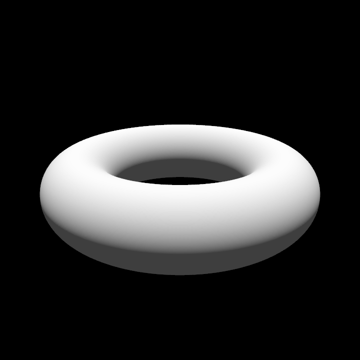
func torus(r1, r2)
    func(p) hypot(hypot(p[..2])-r1, p[2]) - r2

!window size=720
    !canvas3d id=:top samples=4 viewpoint=0;-500;200 fov=0.15
        !light color=0.05
        !light color=0.95 direction=0;0;-1
        !material color=1
            !transform scale=200
                !sdf function=torus(0.75, 0.25)
Note that here torus() is a function that returns an anonymous
function. This anonymous function is set as
the function attribute of !sdf and is repeatedly evaluated to create the
surface. The resulting mesh is cached. SDF functions may capture names – such
as r1 and r2 in this example. Any change to captured values will result
in a new mesh being created. An SDF function cannot access the
state mapping.
If the function attribute is provided, then any sub-nodes are ignored. An
!sdf node with a custom function can also be used nested within another !sdf
node. If used in this way, the maximum, minimum and resolution attributes
are ignored. Nested functions can be combined with transform and operation
nodes.
Signed distance field model hierarchies may also contain the SDF-only !mix
node. This takes two or more child nodes and the following attribute:
weights=WEIGHTSAn n-vector defining the relative weight to apply to each of the sub-models. Default is
1.
The !mix node blends together the signed distance fields of its children
according to the value of the corresponding element of weights, which is
repeated as necessary to match the number of children. The default operation
blends all children together equally. With two children and a weights vector
of 0.2;0.8, the result would be a blend of 20% of the first SDF and 80% of
the second. An individual weight value of zero would ignore a child completely.
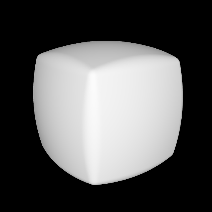
The !mix node can be used to create combined shapes like a partly-spheroid
box:
!window size=720
    !canvas3d id=:top samples=4 fov=0.1
        !light color=1 direction=0;0;-1
        !material color=1
            !transform rotate_x=0.05 rotate_y=0.1 scale=100
                !sdf
                    !mix weights=0.6;0.4
                        !box
                        !sphere
As with constructive solid geometry, SDF hierarchies are cached and may be rendered multiple times with different transforms and materials at low cost. However, as with CSG operations, changing any attribute of a node in an SDF hierarchy will result in a new mesh being calculated. See the note above on Animating CSG operations for a useful workaround.
The resulting mesh of an !sdf node will not have any defined UV coordinates
for texture mapping. The !sdf node supports the model uv_remap attribute
(described in Controlling Model Shading)
as a mechanism to construct these.
Note
The marching tetrahedra method of constructing a surface does not, in general, deal well with sharp corners. If clean, sharp models are required then it is almost certainly a better idea to use the normal mesh-based CSG operations.
Signed distance fields come into their own for creating smooth forms. They are
best used with the smooth, fillet and chamfer-variants of the CSG
operations and/or with custom functions.